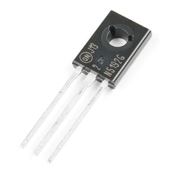
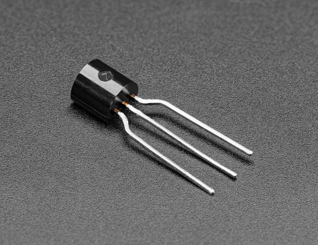
NPN (Negative-Positive-Negative) and PNP (Positive-Negative-Positive) are common types of bipolar junction transistors. Because of their positive and negative doped material texture, they can provide the ability to amplify signals or switch currents efficiently and quickly.
Although these two sensors perform and have similar essential functions, they are sometimes suited to different situations.
When to prioritize using NPN or PNP? In which case should you use both models? What is the main difference between these two transistors?
I will provide you with detailed answers in this article.
NPN Transistor

NPN transistors have n-type and p-type semiconductor materials inside; however, the p-layer is usually thinner than that in PNP. About this transistor thickness, the thickest area is the collector, and the base is the thinnest area.
Its base region is reverse-connected, while the transmitter base region is forward-biased. The forward bias voltage is usually smaller than the reverse bias.
In the junction, the emitter will be in a forward-biased state, and the electrons will likely reach the base to develop an emitter current.
Despite the principle that the electron in the baseband will combine with a hole, the base is, in fact, fragile and doped. The current base forms by combining small holes with electrons.
At the same time, other electrons will pass through the base of the collector to develop a current. Since all the transmitter current flows through the receiver, we have the following:
Transmit current = Receiver current + Base current
PNP Transistor

The PNP construction also includes two basic material blocks, p, and n, so it has three devices, the base, the transmitter, and the receiver. The p-type material is found in the transistor emitter and collector, while its base is an n-type material.
For connection, the transmitter base junction on the PNP follows the forward direction principle, and the receiver base junction is in the opposite direction. The emitter current setting describes the intersection between this part and the base, which repels the charge carrier.
For holes, a p and n-type combination form the base current. The remaining spots will pass through the base region of the negative-bias collector and then be captured by the do-collector.
Similar to the NPN transistor, a complete emitter current flows through the collector circuit. From its operation principle, we get the following formula to calculate the output current:
Transmit current = Receiver current – Base current
Key Difference between NPN & PNP Transistor
We have learned the difference in composition, operating principle, and some critical characteristics between NPN and PNP transistors. Next, let’s review the differences to understand more about these two types of transistors.
1. Symbol

NPN and PNP transistor symbols are similar, but the only difference is in the arrow on the emitter. Precisely, the NPN arrowhead moves outward until the base, while the needle in the PNP moves inward.
2. Full form
The difference between NPN and PNP structure is in the material composition. NPN comes with 2 n-type and 1 p-type semiconductor materials, while PNP has 2 thick layers of n-material and a thin outermost one.
Current flows from collector to emitter in NPN due to positive supply from the base and different electron positions. In contrast, PNP semiconductors are due to the current flowing from emitter to collector due to different hole positions.
3. Current direction
The current direction in these 2 transistors is opposite. When the NPN transistor turns on, a small current will flow from the emitter to the base. And a small current will flow from the bottom to the emitter.
Difference is the transmitter base and receiver base junction. Both NPN and PNP transistors are connected in forward and reverse bias directions.
The diode P pole will join the lively bar, and the N pole will attach to the negative pole in the power supply. Yet, each type has its own connection capacity due to different pole numbers.
4. Turn-on
When you flip the switch, the NPN transistor usually takes longer to switch and navigate than the PNP because it has more electron holes. Hence, the primary charge carrier in the NPN is the electron, not the proton.
Another possible explanation is that the output current in an NPN transistor involves holes, while the electron currents form the PNP.
In short, charge carriers in NPN are mainly electrons, while PNP is holed. Conversely, the minority carrier NPN is the spot, and the PNP is the electron.
5. Inside/Outside current
The PNP forms and develops its internal and external currents thanks to different hole positions and electron flows. On the contrary, the current will produce inside the NPN because the electron flow shifts in many places.
Although there are differences in the primary electrical conduction principles, what they all have in common is the balance of internal and external currents.
You will not be able to detect any difference if you test the amperage of these two areas on both PNP and NPN models.
So, any gap created is related to internal chip system failure.
|
NPN transistor |
PNP transistor | |
|---|---|---|
|
Current direction |
Go outside |
Go inside |
|
Charge carriers |
Electron |
Empty hole |
|
Current direction |
Receiver -> Transmitter |
Transmitter -> Receiver |
|
In the on state |
Sensor generates a positive output |
Sensor generates a signal or negative output |
|
Electron transition time |
Fast |
Slow |
|
Small current |
Emitter -> Base Junction |
Base Junction -> Emitter |
|
Ground signal |
Low |
High |
|
Conductivity |
High |
Relatively low |
NPN/PNP Transistor Applications
NPN and PNP are two applicable transistors in the current circuit design market.
However, NPN is more popular because its n-material transfers electrons faster than p-materials, which generally carry anode currents in holes.
NPN has excellent advantages in high-speed switching and amplifier circuit applications. Besides, NPN transistors are easy to mass produce and are significantly cheaper than PNP-type transistors.
Despite being less popular, many circuits benefit quite a bit from PNP-type transistors. Some circuits can only work with this design.
Specifically, with a class B amplifier, this circuit requires both PNP and NPN transistors to work in parallel to optimize the oscillating signal.
Conclusion
Above is my analysis and comparison regarding the operation, characteristics, and critical difference between NPN and PNP transistors.
I hope that this post can provide valuable information to understand your circuit properly, seamlessly, and consistently. If you have further questions, contact us to receive the most enthusiastic support. Thank you for reading!

